1.1 In order to make the installation of high-density polyethylene wall reinforced pipe (HDPE for short) pipe fast, safe, ensure quality, and realize zero leakage of the whole project, this construction procedure is formulated. All units are expected to comply with the relevant current national regulations in addition to the provisions of this construction procedure, and strictly control the construction quality.
1.2 This procedure is compiled on the basis of relevant provisions of HDPE Pipeline Engineering Technical Specification, Code for Construction and Acceptance of Water Supply and Drainage Pipeline Engineering (GB50268-2008) and China Engineering Construction Standardization Association Standard Buried Polyethylene Drainage Pipeline Engineering Technical Specification (CECS164:2004).
Ii. Pipeline handling and Storage:
2.1 Pipes are mainly loaded and unloaded by mechanical means. Belts, slings or lifting ropes with good flexibility should be used during loading and unloading.
2.2 Two support points shall be adopted during pipeline loading and unloading, and the two support points shall be placed at a quarter of the pipe length to keep the pipeline stable.
2.3 In the process of pipe loading and unloading, the pipe impact or fall should be prevented. HDPE pipe fitting suppliers should pay special attention to pipe end protection. If there is any abrasion, contact the manufacturer in time for proper handling.
2.4 When the pipeline is directly placed on the ground, the ground shall be flat, there shall be no stones or sharp objects which may easily cause damage to the pipeline, and measures shall be taken to prevent the pipeline from rolling.
2.5 When the pipes of different diameters are stacked, the large and heavy side should be put down and gently placed on the top, and the two sides of the pipe should be blocked with wooden boards. Pay attention to the bearing capacity of the bottom pipe when stacking, stacking height is not more than 3 meters.
2.6 Long-term open flame is strictly prohibited near the pipeline.
Three, trench excavation:
3.1 Trench excavation shall be carried out according to the construction drawings at design time.
3.2 During trench excavation, the undisturbed soil of 0.2-0.3m above the designed elevation of the bottom of the trench should be retained and cleaned manually before pipe laying. However, it is generally not appropriate to dig below the designed elevation of the bottom of the trench. For local over-digging, sand or original soil should be used to fill in the trench and layered compaction.
3.3 If there are hard objects such as rocks or foundation rocks, semi-rocks or gravel buried at the bottom of the ditch that are not easy to be removed, the part of the overdug below the elevation of 0.3-0.2m shall be removed and layered with sand or original soil. The density should not be lower than the natural foundation density. When there is groundwater at the bottom of the tank or the soil moisture content of the foundation is large, it can be backfilled with natural sand and stone.
3.4 A small transverse groove with a width of 0.5m and a depth of 0.3m should be excavated at the bottom of the connection of each pipe to facilitate heat dissipation and groundwater reduction, avoid the grounding of electric fuse, and prevent the welding joint from being completely fused due to the temperature transfer of the welding joint to the ground.
Four, pipeline connection
4.1 Pipe connection and installation shall be carried out after pipe inspection and acceptance
4.2 Mechanical lifting equipment should be used for pipe connection. Hoisting belts or ropes should be used during hoisting, and wire ropes are strictly prohibited. During pipe lowering, the pipes are strictly prohibited from falling freely from top to bottom, and stones and other objects should be prevented from striking the pipe body.
4.3 Before pipe lowering, 2 hoisting belts or ropes should be placed at the bottom of the ditch in advance. The length of hoisting belts or ropes should meet the requirement that the round sleeve of hoisting belts or hoisting ropes can be placed in the first quarter of the pipe to be installed, and ensure that the 2 hoisting belts or hoisting ropes are parallel to the pipe laying direction at the vertical tangent line of the pipe section respectively under the action of manual hoist. And ensure that when the pipe socket is connected, the tightening amount and speed of the lifting belt or lifting rope are maintained so that the socket is evenly inserted into the socket.
4.4 When running the pipe, the socket should be in the direction of the water, and the socket should be in the direction of the opposite water.
4.5 The socket must be cleaned before the pipe connection. Dirt and sediment are not allowed to enter the socket during the connection. Socket spacing should be about 10mm.
4.6 Special personnel shall direct the pipe docking, and the hoisting equipment and manual hoist shall coordinate with each other for the docking. It is not allowed to place the pipe at the bottom of the ditch and only use the above two hoisting belts or hoisting ropes for pipe connection.
4.7 Design elevation and design center line shall be retested after pipeline connection is in place.
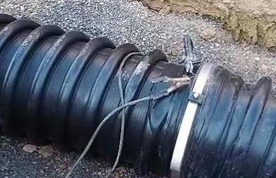
5. Electric melting of pipelines
5.1 Before pipeline electric melting, check whether there are sundries in the socket and whether the electric fuse is disconnected or grounded. If the above phenomena exist, hot melting is strictly prohibited.
5.2 Check the pipeline axial direction before electromelting, and adjust it in time. After passing the inspection, electromelting can be carried out.
5.3 The operators engaged in pipeline connection shall undergo special training and pass technical assessment before starting the operation.
5.4 The inner support ring of the nozzle should be placed 50mm away from the inner edge of the socket (except for DN900 pipe less than) and the outer tightening band should be firmly in place.
5.5 During electrofusion connection, the electrofusion connecting machine and tool shall be correctly connected with the electrofusion joint. During the connection, the pipe shall not be moved or any external force (except the support ring) shall be applied to the connector.
5.6 Tighten the internal support ring every 10 minutes during power-on welding.
5.7 Welding requires 380V power supply with a power of 10 kW. During welding, polyethylene melt drops are generated at the external heating wire.
Welding parameters of electric fusion welder
Ambient temperature 10 ° C to 20 ° C
The ambient temperature is 20 ° C to 30 ° C
Return,
(mm)
voltage
(v)
Time (min)
Specification (mm)
voltage
(v)
Time (min)
DN300
12 to 15
12-17
DN300
12 to 15
10-14
DN400
13 to 17
15-20
DN400
13 to 17
12 to 15
DN500
15-20
17-22
DN500
15-20
13 to 18
DN600
18 to 22
20-25
DN600
18 to 22
15-20
DN700
20-25
23 to 28
DN700
20-25
18 to 23
DN800
25 to 30
25 to 30
DN800
25 to 30
20-25
DN900
28 and 33,
27-32
DN900
28 and 33,
22 to 28
DN1000
30-35
30-35
DN1000
30-35
26-32
DN1100
35-40
33-38
DN1100
35-40
28 and 35
DN1200
DN1200
DN1300
38-45
35-40
DN1300
38-45
33-40
DN1400
DN1400
DN1500
45 to 50
50-65.
DN1500
45 to 50
50 to 60
DN1600
DN1600
DN1800
DN1800
DN2000
50 to 55
60-70.
DN2000
50 to 55
55-65.
DN2200
DN2200
DN3000
45-50(Two welders working at the same time, parameters refer to DN1500)
50-65.
DN3000
45 to 50
50 to 60
Note: 1. When the ambient temperature is between 5 ° C and 10 ° C, extend the welding time for 3-5 minutes according to the ambient temperature between 10 ° C and 20 ° C, while the data of each specification and voltage remain unchanged.
2. In the process of current welding of the welder, the change of current is proportional to the change of voltage, so the change range of current in the process of welding is large, which does not affect the welding effect.
3. The onsite power cable should match the equipment ratio. If the above conditions cannot be met due to the discrepancy between the power cable and the equipment ratio, the onsite technician should adjust the welding time and voltage according to the actual situation.
5.8 After the electrification is completed, take off the electric melting equipment and properly tighten the tensioning belt to allow the pipe connection to cool naturally. During the natural cooling period, keep the tensioning belt and support ring and do not move the pipe. The cooling time is about 20-40 minutes.
5.9 Check the appearance quality of the joint after electromelting.
Vi. Pipe chest support (≥DN800)
6.1 Radial support shall be carried out for pipelines after cooling
6.2 Each HDPE pipe uses 3-point supports.
6.3 Pipe support must be completed before backfilling.
6.4 Check the supporting condition when the backfilling reaches more than half of the pipe. If the backfilling quality is not up to the standard due to the strong supporting force of the wooden side, backfill the pipe again. No support or toppling is normal.
6.5 Pipe support can not be removed until the upper part of the pipe top is backfilled and tamped.
Seven, groove backfill
7.1 Backfill of pipe axils must be tightly packed, compacted and kept in close contact with the pipe. Vibrators must not be used to prevent pipe drift.
7.2 The pipes shall be backfilled in time after welding and cooling, especially in the rainy season to prevent the occurrence of drift pipes.
7.3 Trench backfilling construction must be carried out simultaneously on both sides of the pipeline, and unilateral backfilling is strictly prohibited. The height difference between the two sides of the filling soil should not exceed one thickness, and the filling soil should be rammed in layers. The thickness of each layer is determined according to the used compaction tools, required compaction tools and required compaction density. Thickness of soil spread for common compacting tools.
Select according to the figures in the table below
Tool for compaction
Cover thickness (mm)
Wood tamper, iron tamper, plate vibrator
200 or less
Rapid impact rammer, thermal rammer
200-250.
7.4 When backfilling soil or other backfilling materials are transported into the tank, the pipe body and its interface shall not be damaged and shall comply with the following regulations
(1) The backfill material shall be transported to the tank according to the amount of the thickness of a layer of virtual bedding, and shall not be piled within the scope of affecting compaction.
(2) The backfill material on both sides of the pipe and within 0.5m above the top of the pipe should be transported symmetrically into the groove by both sides of the groove, and should not be thrown directly on the pipe. When backfilling other parts, it should be uniformly transported into the groove, and should not be pushed in a centralized way.
(3) Backfill materials that need to be mixed shall be mixed evenly before being transported into the tank, and shall not be mixed in the tank.
7.5 Compaction of trench backfill shall comply with the following requirements.
(1) Backfill compaction should be carried out layer by layer, and shall not damage the pipeline.
(2) Light tamping should be used for compaction above the central axis of both sides of the pipeline and within the range of 0.5m of the pipe top. The height difference of the compaction surface on both sides of the pipeline should not exceed 0.3m
(3) There are two rows of pipes in the same trench, but the bottom of the foundation is located in the same plane. The backfilling compaction between the pipes should be carried out symmetrically with the backfilling compaction between the pipes and the wall of the groove.
(4) The segmented backfill pressure is real time, and the adjacent joints should be in step form and not leak tamping.
(5) Using wood rammer, rapid impact rammer and other compaction tools, should be rammed together.
7.6 In the subgrade range, the compaction density (all referred to as "compactness") of backfill soil above the pipe top shall not be less than 90%. The compaction degree of backfill soil on both sides of the pipeline shall not be less than 95%.
7.7 Backfilling around inspection Wells, connecting Wells and other well chambers shall meet the following requirements
(1) Backfill around the well chamber should be carried out at the same time as backfill in the pipe grooves. When it is inconvenient to backfill at the same time, leave a step - shaped joint.
(2) The backfill material should be compacted closely with the shaft wall.
7.8 In order to close the water and facilitate inspection, partial backfill can be carried out on the pipeline, leaving the welded part unfilled and the rest of the pipe backfill and tamp, but leave the step shaped joint. It is strictly prohibited that the inspection well is damaged due to the influence of temperature difference caused by not backfilling.
Viii. Pipeline protection after construction:
8.1 It is strictly prohibited to excavate the backfilled pipes unilaterally and drain the pipes in open ditches above them to prevent the backfill soil from loosening and causing pipeline deformation.
8.2 For pipelines crossing the road or under the roadbed, if there are heavy vehicles passing through when the road is not well paved, protection measures must be taken.
8.3 When the backfill soil height of the pipeline is not enough, it is strictly prohibited for all vehicles to pass over the pipeline (the backfill soil height shall be in accordance with the design requirements).
8.4 Pile driving and soil excavation disturbance around the pipe should be avoided as far as possible.
8.5 The water temperature of the pipe shall not be higher than 45℃ during use.
For matters not covered, please refer to the design requirements and China Engineering Construction Standardization Association standard "Buried polyethylene Drainage pipe Engineering Technical Regulations".
Note: No one is allowed to use the welding equipment without the permission of the technical personnel of the manufacturer, otherwise all consequences caused by the parties shall be responsible for.